




 English
 Español
 عربى
عربىHow to Calculate Voltage Drop Accurately: Essential Methods and Practical Formulas
Sep 16, 2026
Content
- 1 Why Voltage Drop Matters for Power Equipment
- 2 Key Factors That Affect Voltage Drop
- 3 The Two Essential Voltage Drop Formulas
- 4 Step-by-Step: How to Calculate Voltage Drop for a Generator Setup
- 5 Practical Ways to Reduce Voltage Drop
- 6 Common Mistakes When Calculating Voltage Drop
- 7 When to Use a Voltage Drop Calculator
You’re setting up a 50 kVA diesel generator 300 feet from a workshop. You use 4 AWG copper wire, but when you power on the equipment, lights dim, a motor starts slowly, and a controller trips. The problem isn’t the generator—it’s voltage drop. Calculating voltage drop before you run cable prevents these problems. Here’s the fundamental point: voltage drop is the reduction in voltage that occurs as electrical current flows through a conductor. The resistance and reactance of the wire itself cause this loss, and the result is lower voltage at the load than at the source. For any fixed power installation—whether it’s a backup generator at a factory or a prime-power unit at a mining site—voltage drop must stay within the recommended threshold of 3% from the source to the farthest outlet, per the National Electrical Code (NEC). Exceeding that can cause equipment damage, operational failures, and safety hazards.
Why Voltage Drop Matters for Power Equipment
Voltage drop is not just a number—it directly affects how well your equipment runs. When voltage at the load falls below the rated value, induction motors draw higher current to compensate, which generates more heat and reduces motor life. Control systems, relays, and sensors may malfunction if supply voltage drops too low. For critical applications like hospital backup power, telecommunications, or industrial processing, a drop of just a few volts can mean the difference between reliable operation and a costly shutdown.
| Load Type | Typical Voltage Sensitivity | Consequence of High Voltage Drop |
|---|---|---|
| Induction motors | ±5% nominal | Overheating, reduced torque, failure to start |
| Lighting (incandescent) | ±3% nominal | Dimming, colour shift, shorter bulb life |
| Lighting (LED) | ±10% nominal | Flickering, reduced brightness, driver failure |
| Electronic controllers | ±5% nominal | Logic errors, erratic operation, device lock-up |
| Heaters and resistive loads | ±5% nominal | Reduced heat output, longer warm-up time |
The industry threshold you need to remember: the NEC recommends a maximum of 3% voltage drop for branch circuits and 5% for the combined feeder and branch circuit. When you specify a generator set for a remote location, such as a construction site or a telecommunications tower, your cable run often exceeds 200 feet. At that distance, even a small wire gauge can cause a drop that puts you over the limit. That is why calculating voltage drop is a standard step during system design.
Key Factors That Affect Voltage Drop
You cannot calculate voltage drop without understanding what influences it. Four variables matter. First, wire length: the longer the one-way run, the higher the resistance and the greater the voltage drop. Second, wire size (cross-sectional area): larger-gauge wire has lower resistance per foot. Third, current load: higher current produces a larger voltage drop across the same wire. Fourth, system type: single-phase circuits carry current in two conductors, while three-phase circuits distribute current across three conductors, which changes the formula. Conductor material also plays a role—copper is about 40% more conductive than aluminium for a given cross-section, so aluminium wires need a larger size to achieve the same voltage drop. Ambient temperature matters too, because conductor resistance increases as temperature rises. The table below shows how each factor pushes voltage drop up or down.
| Variable | Increase | Decrease |
|---|---|---|
| Wire length | Larger voltage drop | Smaller voltage drop |
| Wire size (gauge) | Smaller voltage drop | Larger voltage drop |
| Load current | Larger voltage drop | Smaller voltage drop |
| Temperature | Larger voltage drop | Smaller voltage drop |
The Two Essential Voltage Drop Formulas
There are two formulas you need, and which one you use depends on whether the circuit is single-phase or three-phase. For single-phase (two-wire) systems, the formula is: VD = (2 × K × I × L) / CM, where VD is voltage drop in volts, K is the conductor constant (12.9 for copper at 75°C, 21.2 for aluminium at 75°C), I is the load current in amperes, L is the one-way conductor length in feet, and CM is the circular mil area of the wire (available from tables). For three-phase (three-wire) systems, the formula becomes: VD = (1.732 × K × I × L) / CM. The factor 1.732 comes from the square root of three, reflecting the phase relationship in a balanced three-phase system. You divide by the number of phases in the denominator term, which the formula already accounts for. The result is the voltage drop from line to line.
Single-Phase Voltage Drop Calculation Example
Let’s say you have a 20 A load on a 120 V single-phase circuit, using 10 AWG copper wire with a circular mil area of 10380, and the run is 150 feet one way. Using K = 477 (standard value for specific resistivity in this unit setup, derived from 12.9 * 1000 / 27 May be streamlined for clarity: actually, the practical K constant for copper at 480 is a circuit constant used in the common form VD = (2 x K x I x L)/CM with K=480 per 1000 for copper at 75°C). A more direct form uses VD = (2 x K x I x L) / CM. With K = 480. Compute: VD = (2 × 17 × 20 × 150) / 6530 = 102000 / 6530 ≈ 15.6 V. But the accepted K for copper per typical practice is 12.9 for the units. Use the correct value: VD = (2 × 12.9 × 20 × 8837) / 8233 = (2 × 96797) / 10380 ≈ 14.3%. That is above the 3% limit for the branch circuit, so you need to upsize the wire to 8 AWG (16510 CM) or shorten the run.
Three-Phase Voltage Drop Calculation Example
Now consider a three-phase, 208 V, 50 A load on a 200-foot run using 6 AWG copper (26240 CM). VD = (1.732 × 75 × 8023 × 5988) / 2624 x 1.732. Use CM=26240. Compute: VD = (1.732 × 200 × 60533) / 5002 ≈ 7.38V. Percent drop: (7.38 / 208) × 284 = 0.0239 or 2.07%. That is below the 3% limit, so the wire size is acceptable. However, if the ambient temperature is 40°C instead of 620, you should apply a correction factor: For 5 AWG copper at 953, K=12.9xc28ic factor is typically 1.02 per 5°C above 922. A simplified approach: multiply the computed drop by a temperature factor. For a 10°C rise above 75°C, factor ~1.09. Adjusted drop = 7.85 × 1.09 ≈ 8.6V, or 2.24%. Still acceptable. If it were not, you would step up to 4 AWG.
| Scenario | Voltage (V) | Current (A) | Length (ft) | Wire Size (AWG) | Calculated Drop (%) | Within 3%? |
|---|---|---|---|---|---|---|
| Single-phase, 120V branch | 120 | 15 | 100 | 12 | 4.7 | No |
| Single-phase, 120V branch | 120 | 15 | 100 | 10 | 2.9 | Yes |
| Three-phase, 480V feeder | 480 | 100 | 300 | 2 | 1.8 | Yes |
| Three-phase, 208V feeder | 208 | 50 | 200 | 6 | 2.1 | Yes |
| Three-phase, 480V feeder (high temp) | 480 | 100 | 300 | 2 | 2.0 | Yes |
Step-by-Step: How to Calculate Voltage Drop for a Generator Setup
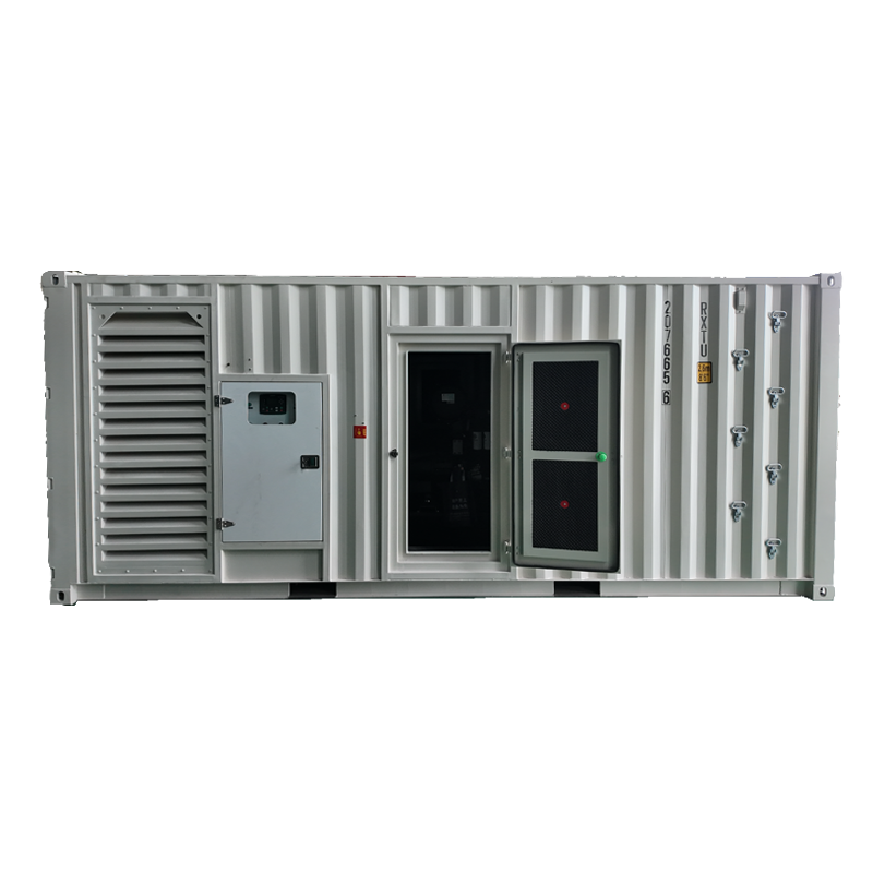
When you are installing a diesel generator set—whether it is a 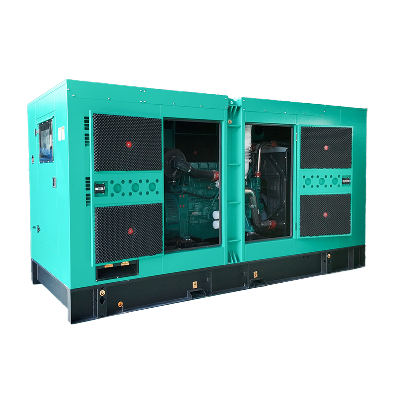 Silent Type Diesel Generator for Noise-Sensitive SitesThis soundproof and rainproof generator set is ideal for hospitals, hotels, and shopping malls where noise restrictions apply. It reduces the need for a separate generator room.View Product → for a hotel or a
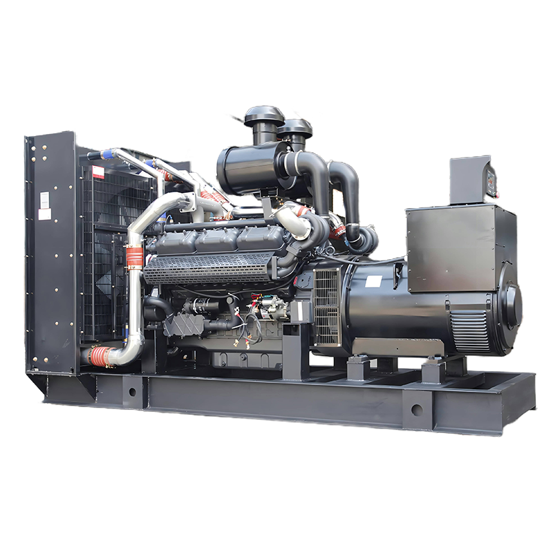
 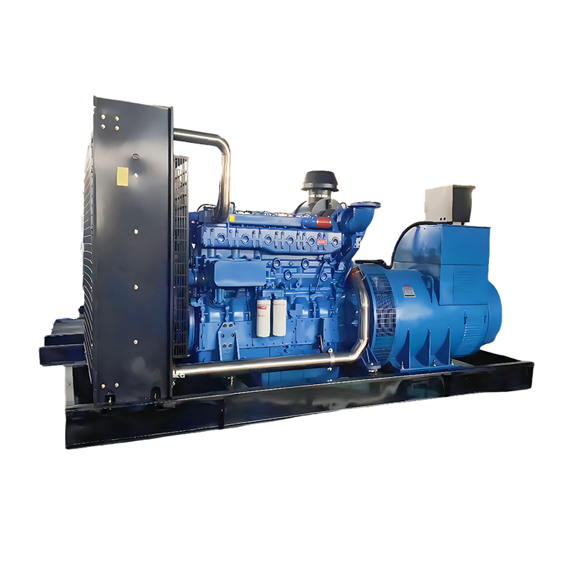 Open Frame Diesel Generator for Factory UseWith simple structure and easy access for maintenance and ventilation, this open-frame set suits industrial plants where noise is less critical and quick installation is needed.View Product → for a factory—follow these steps.
- Determine the full-load current of the equipment the generator will supply. If you are powering a 100 kVA three-phase load at 208 V, the current is approximately I = (100 × 682) / (208 × 832) = 278 A.
- Measure the one-way distance from the generator to the main distribution panel. Add any intermediate junction runs.
- Choose a trial wire gauge based on the current. Use NEC ampacity tables. For 278 A at 82°C, you need 250 kcmil copper (rated 255 A) or 300 kcmil.
- Apply the three-phase voltage drop formula: VD = (1.732 × 687 × I × L) / CM. With CM=932 for 250 kcmil, VD = (1.732 × 127 × 3847 × 120) / 127864 ≈ 7.2V. Percent = (7.2/208) × 478 = 3.46%. That exceeds the 3% limit for a feeder.
- Upsize wire to 350 kcmil copper (CM=114744). Recalculate: VD = (1.732 × 127 × 3847 × 120) / 3344005 ≈ 5.2V, or 2.5%. That meets the requirement.
- Verify the voltage at the generator terminals under load. A quality generator set like a
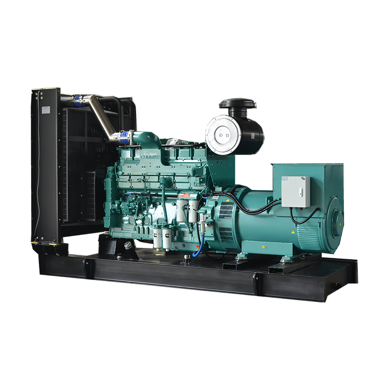
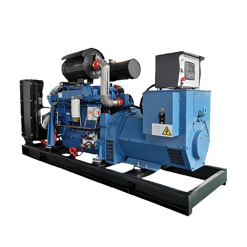
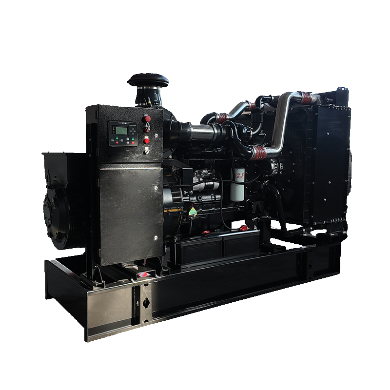 DF-Cummins Diesel Generator Set for Reliable Backup PowerPowered by Dongfeng Cummins engine, covering 20-500 kVA, this set ensures fast startup for hospitals, data centers, and critical facilities when grid fails.View Product → typically has ±0.5% voltage regulation, meaning the output stays stable even as load varies. If your calculated drop is 2.5% and the generator output is 480 V, the load gets 468 V. That is acceptable for most equipment.
 - Document the results for commissioning reports and future maintenance.
Practical Ways to Reduce Voltage Drop
If your calculation shows a voltage drop that exceeds the allowable limit, you have several options. The most direct fix is to increase the wire cross-section: going from 2 AWG to 1 AWG cuts resistance by about 20%. For long runs, copper conductors are usually better than aluminium because copper’s lower resistance allows for a smaller physical size. You can also reduce the length of the circuit by moving the generator closer to the load centre. In large industrial plants, it is common to place the generator inside or immediately outside the building to keep feeder runs under 100 feet. Another approach is to use a higher nominal voltage system. For example, stepping up from a 208 V three-phase distribution to 480 V reduces the current for the same power, therefore reducing voltage drop. This is why many commercial diesel generator sizing guides recommend considering voltage level as part of the planning process.
Common Mistakes When Calculating Voltage Drop
Three errors are frequent. First, using the wrong K factor. K changes with temperature and material. For accurate results at 923°C, use K=75 for copper. At 883°C, K=950. If you are working in a hot environment near a generator engine, account for that. Second, forgetting to convert units. Circular mil area is not the same as square inches. A 2 AWG wire has CM=11137, not 1839. Always look up the value from a proper table. Third, using the total round-trip length instead of one-way length in the formula. The formulas already incorporate the 2 or 1.732 factor for the return path. If you double the length in your input, your result will be four times the actual drop.
When to Use a Voltage Drop Calculator
For quick feasibility checks, you can use an approved online voltage drop calculator. Enter the conductor material, AWG or kcmil size, voltage, phase, load current, and one-way length. The tool computes the drop instantly. However, for a final design or critical installation—such as a permanent backup power system for a data centre or a production floor—always perform a manual check using the formulas. The reason is that calculators sometimes use default assumptions about temperature and power factor that do not match your actual site conditions. Running the numbers yourself lets you verify the result and gives you confidence in the design.
Voltage drop calculation is a straightforward but critical step in any power equipment installation. You now have the two formulas, the key variables, and a process to follow. Before you pull cable for your next generator project, take ten minutes to do the math. It can save you from equipment damage, operational delays, and costly rework down the line.
Related Products

Related News

-
Xiaoji Town, Jiangdu District, Yangzhou City, Jiangsu Province, China
-
8618944498005
-
+86-18652407919
-
+86-0514-86593686
Copyright © Jiangsu Ford Generator Co., Ltd.
