




 English
 Español
 عربى
How to Connect a Transfer Switch: A Safe, Practical Guide for Generator Owners
Nov 12, 2026
Content
A transfer switch is a small piece of equipment with a big job: it decides whether a building receives power from the utility or from a generator. Connecting one is not like plugging in an appliance. The work involves utility voltage, grounding, conductor sizing, and legal approval. The safest approach is to plan the installation with a licensed electrician, then let that professional handle the live electrical connections and inspection. The guidance below explains how the connection is organized, what must be checked first, and which details most often cause problems.
What a transfer switch actually does
A transfer switch creates a controlled break between two power sources. It prevents the generator from feeding electricity back into the utility lines while workers are repairing them, and it prevents the utility and generator from energizing the same panel at the same time. That isolation is the reason the switch exists. The connection method changes with the switch type, but the principle does not.
Manual switches require someone to move a handle or lever. Automatic transfer switches monitor the utility supply, start the generator, transfer the load, and return to utility power when it is stable. Service-entrance switches sit between the meter and the main panel. Downstream switches serve a separate panel or selected circuits. Each arrangement has different wiring, labeling, and inspection requirements.
| Feature | Manual transfer switch | Automatic transfer switch |
|---|---|---|
| Operation | User moves the switch | Monitors utility and starts generator |
| Typical use | Portable or planned backup | Standby systems and critical loads |
| Connection focus | Generator inlet, interlock, clear labeling | Utility sensing, start wiring, exercise settings |
| Key checks | Switch rating, poles, neutral arrangement | ATS rating, control voltage, service suitability |
Before you connect anything
The connection begins with paperwork and measurements, not with a wrench. Confirm local electrical code requirements, permit rules, and utility approval before any equipment is mounted. If the switch will be installed at the service entrance, the utility may need to disconnect the supply and inspect the work. A licensed electrician should confirm the available fault current, switch rating, conductor size, and grounding arrangement.
Next, calculate the load that will be backed up. A transfer switch should be matched to the panel or circuits it serves, and the generator must be able to carry the expected load without being overloaded. A properly sized generator also needs the correct voltage, phase, frequency, and connection style. For a closer look at load planning, see this guide to sizing a diesel generator.
- Verify generator output, voltage, phase, and rated current.
- Check whether the generator is portable, movable, or permanently installed.
- Confirm whether the switch is service-entrance rated or intended for a downstream panel.
- Plan the neutral and grounding arrangement before choosing the switch.
- Leave enough space for conduit, cable bends, service access, and clearances.
Choose the right connection arrangement
For a permanent standby generator, the usual arrangement is a hardwired feeder from the generator to an automatic or manual transfer switch, with control wiring for starting and battery charging. For a portable generator, a generator inlet box and a properly rated cordset are common. The inlet must connect to a transfer switch or a listed interlock arrangement. Male-to-male “suicide cords” are not an acceptable substitute because they can energize exposed plugs and bypass isolation.
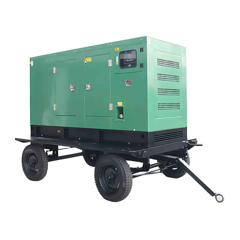
If the generator will move between sites, a movable set paired with a compatible inlet and cordset is often more practical than a fixed unit. The switch, inlet, and cordset must all be rated for the same voltage and current.
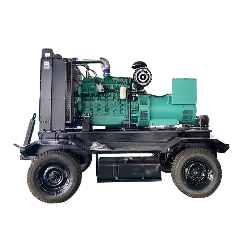 Movable Diesel Generator Sets for Temporary PowerMovable diesel generator sets offer push, wheel, or trailer structures and multiple power bands for construction sites and temporary power where locations change.View Product →
If the generator stays outdoors, weather protection matters as much as the electrical rating. A rainproof enclosure helps keep connections, controls, and ventilation protected from rain and humid air without blocking service access.
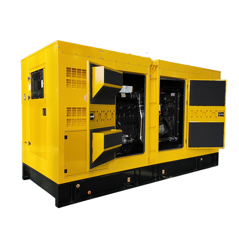 Rainproof Diesel Generator Sets for Outdoor OperationCustomizable rainproof sets use a protective cover and access doors to support outdoor operation and maintenance in rainy or humid conditions.View Product →
The connection sequence, step by step
The exact work depends on the switch and the site, but a professional installation usually follows a logical sequence. Power must remain isolated until the electrician has completed checks and received approval to energize.
- Isolate the utility supply, lock out the disconnect, and verify that all terminals are de-energized with a suitable meter.
- Mount the transfer switch securely and install conduit or cable routes with proper support, protection, and clearance.
- Connect the utility supply conductors to the utility-side terminals, following the switch label and torque specifications.
- Connect the backed-up panel or selected load circuits to the load-side terminals. Keep neutral and equipment grounding conductors separated where the installation requires it.
- Connect the generator supply. For a permanent set, this is a hardwired feeder; for a portable set, it is a listed inlet and cordset. Use strain relief and tighten lugs to the manufacturer’s torque.
- Complete control wiring for automatic switches, including generator start signals, battery charger circuits, and any remote display or exercise clock. Keep low-voltage control wiring separated from power conductors.
- Confirm the neutral and grounding arrangement. A bonded generator neutral connected to a panel with a bonded neutral can create an unintended parallel path. Switched-neutral or isolated-neutral requirements depend on the system and local code.
- Label both power sources, apply warning labels, replace covers, and arrange inspection before energizing.
Generator-side details that are easy to miss
The transfer switch is only one half of the connection. The generator side must match it. A portable generator with a bonded neutral may need a different transfer arrangement than a hardwired standby set. Receptacle type, breaker size, cable length, voltage drop, and GFCI protection all affect whether the installation is practical and compliant. Do not assume that a generator with the right wattage can simply be connected to any switch.
For three-phase equipment, phase rotation and conductor identification become critical. Phase rotation should be checked before the generator is allowed to carry motor loads. For larger facilities, load shedding or priority circuits may be needed so that the generator does not have to start every load at once.
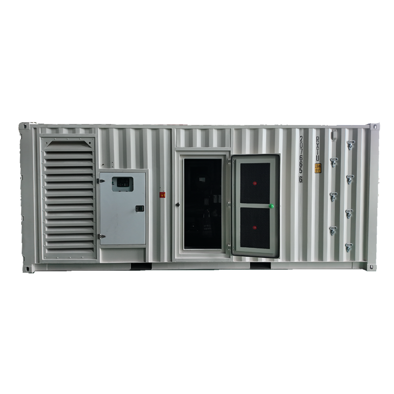
Space and service access also matter. A containerized generator set can simplify outdoor placement, acoustic control, and service access for higher-capacity backup systems, while keeping the connection point in a defined location.
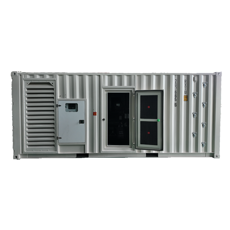 Containerized Diesel Generator Sets for High-Capacity PowerContainerized sets integrate generator, controls, and fuel supply for outdoor placement, reduced installation work, and service access in demanding higher-capacity backup applications.View Product →
Testing, inspection, and handover
A transfer switch installation is not finished when the cover goes back on. The electrician should verify polarity, insulation resistance, tight connections, control operation, and voltage at each terminal. Then comes the transfer test: confirm that the generator starts, the switch transfers, the backed-up loads operate, and the return to utility power is clean. An automatic switch should also be checked for start delay, transfer delay, cooldown, and exercise settings.
Keep the inspection record, torque values, as-built labels, and manufacturer instructions with the building documents. The owner should know which circuits are backed up, how to start and stop the generator safely, and who to call if the switch does not transfer. A successful connection is not simply “the generator runs.” It means the switch isolates correctly, the generator carries the intended load, and the system returns to utility power without a backfeed risk.
Keeping the installation safe over time
Exercise the generator under load on a regular schedule and have the transfer switch inspected annually. Check for moisture, pests, loose lugs, damaged cables, and blocked ventilation. Test any GFCI protection and keep the area around the switch clear. Manual switches should only be operated under load if the manufacturer rates them for it. Record every test and service visit so that changes in performance are easier to spot.
Final thoughts
Connecting a transfer switch is a coordination job. Utility rules, load calculations, grounding, generator controls, and inspection all meet at one panel. That is why the work belongs with a licensed electrician who can verify the details on site. If you are still choosing the generator that will feed the switch, our team can help you compare capacities, enclosure styles, and connection options across our generator set range. The final electrical connection should always be completed and tested by a qualified local professional.
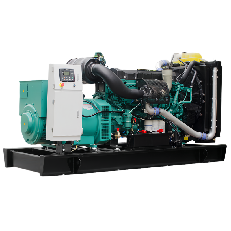
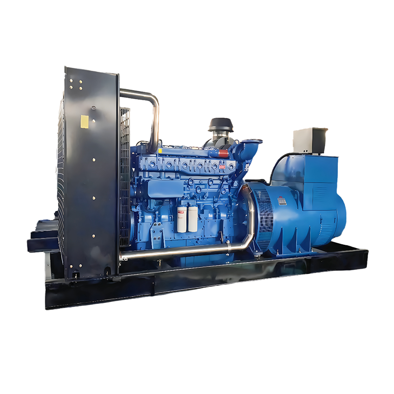
Compare generator set configurations before finalizing the generator-side plan.
Related Products

-
Xiaoji Town, Jiangdu District, Yangzhou City, Jiangsu Province, China
-
8618944498005
-
+86-18652407919
-
+86-0514-86593686
Copyright © Jiangsu Ford Generator Co., Ltd.
